 printable version printable version
Removing and installing drive the power steering
| Fig. 5.11. The components of the steering mechanism: 1 - hex bolt; 2 - the screen; 3 - the shield; 4 - universal joint; 5 - hex bolt; 6 - assisted steering; 7 - sub-frame; 8 - hex bolt; 9 - Self-locking nut; 10 - Self-locking nut; 11 - the case of the wheel bearing; 12 - penstock; 13 - hex bolt; 14 - return line; 15 - cap bolt to 30 N ??? m; 16 - a sealing ring
|
Withdrawal Remove the wheels.
ATTENTION Switchable stabilizers before starting work to include. Otherwise inadvertent inclusion of stabilizers can lead to injury. |
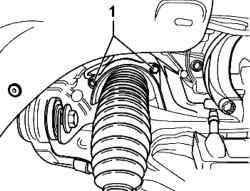
Hold the feed and drain the hose clamps hose. Extract the tie rods from the wheel bearing housing. Unscrew the tip of the left tie rod. Remove the bracket 1 pipeline hydraulics.
Remove the pressure and drain pipes 2 from the steering mechanism (Fig. 5.12). Turn the steering to the left until it stops. If present, remove the shield from the steering mechanism (2 screws). Remove the bolt of the universal joint of the steering mechanism and remove the joint from the steering mechanism.
Move the steering to the right side of the vehicle (Fig. 5.14). Turn left down the track rod. Then remove the steering mechanism in the direction to the left side of the car and down.
Setting Install in reverse order, with the following should be considered. Bleed the steering system Check steering system for leaks Check the oil level of the hydraulic system and top up if necessary Perform basic configuration sensor steering angle.
Tightening torques The pressure and drain pipes on the steering mechanism - 30 Nm. Universal joint to the steering mechanism (use new screw) - 40 Nm + 90 ?°. The screen on the steering mechanism (if available) - 10 Nm. Arm to the wheel bearing housing (use a new nut) - 90 Nm.
| 


